Friday, April 14, 2023

Luxman 507ux Empower Project

The goal of this project was originally to put in a tighter feeling IEC inlet than originally provided.  The lack of a ground pin really leaves one with the feeling that your power plug is not gripping as well as it should be, and indeed, with heavy power cords it was unusually hard to keep a solid AC connection. 

The simple goal morphed into making more modifications: 

  • New quick disconnect IEC C16 inlet replacing hard soldered C18
  • 2x 0.01uF bypass caps replaced by single 0.022uF
  • Wiring upgraded from 20 to 14 gauge as much as possible. 
  • Ensure the black wire was actually connected to the line input, so a blown fuse would disconnect the line and not the neutral.  Not sure if this is a problem to Luxman amps that is unique to the US. 

I found out three things I wish I had not known:

  1. Wiring from main transformer to inlet is 20 gauge
  2. The wrong wire was fused, at least for the US
  3. The main fuse is 15A, very high for an amp rated for 350 Watts using 20 gauge inlet wiring.

After re-assembly I can say that the new IEC connector feels somewhat better than the original in terms of grip confidence, and flipping which wire was fused is a long term safety issue that I'm glad I found, but may have never noticed.  I'll post more if I find the increased wire thickness actually improved sound quality.  

A new bypass cap was needed because the entire original inlet assembly had to be removed and was not easily reused without a wave solder machine.  Plus, now I had an excuse to use far thicker power cables.


The original 2x 0.01uF X2 (safety) caps were replaced by a single yellow 0.022uF connected at the input crimp connectors.  The inlet ground pin is left disconnected, but shrink wrapped out of an abundance of caution.

On the top left you can see the black and white wires next to the fuses.  On the bottom right you can see the new inlet with the blue quick disconnect pins attached along with the decoupling capacitor. 


The end of the power cables is the limiting factor.  It appears to be a Molex Spox connector which I believe is limited to 18 gauge only. Even if I had the $700 Molex crimper I'd not be able to do much about the wire gauge anyway.  If I had a thousand hours of course the solution is to remove the entire Molex connector and replace with something capable of handling a 14 gauge wire. 

Here you can see a close up of the inlet section: 


Effort Level

For some silly reason I had hoped this would be a 15 minute project.  I'd unscrew the inlet, pull it out and replace it, shove it back into my rack.  No, nothing like that.  At the end of the day I needed to remove the entire bottom plate and essentially break the original assembly off the inlet before I could think about replacement. 

Along the way I broke a wire saddle and the cosmetic cover on the hockey-puck like feet came unglued. I also discovered things I wish I had not known and could have probably lived happily not knowing about them.  Alas, once seen I had to change things.  

You can replace the inlet with a lot less effort than I did here.  In case you must follow in my ill-advised path here is the disassembly instructions: 

  1. Remove the bottom cover.  
  2. Clip the wires at the white connector below the inlet.  Do NOT clip them at the other end.
  3. Use a large flat heat screw driver and wedge it between the back of the IEC connector and the PCB, and twist firmly.  You are pulling the pins out of the inlet by force.
  4. Unscrew the IEC connector from the back of the case.
  5. Pull the other end of the cable off the PCB.  You may need to pull on the Molex latch a little.  It's more of a friction fitting as opposed to a latch. 
I leave the re-assembly part of the project up to the reader. 

Thursday, April 13, 2023

Luxman 507ux - AC Inlet Mistake

 It's hard to post when you think you've caught a brand like Luxman in a simple engineering mistake, but since getting in touch with them seems overly complicated I'm just going to blog about it and hope some one in the Internet knows someone at Luxman like CEO Tatsuya Sueyoshi and can have them reply.

The issue that I'm pretty sure of is that for the US, at least, the wiring harness from the AC inlet to the main power board causes the wrong side to be fused. 

In the US, only one of the 2 AC prongs has voltage, it's called the line.  The other is called the neutral. We typically fuse the line, the idea being that if a fuse blows the minimum amount of circuits still have power applied.  If we do the opposite (as in the case here) and fuse the neutral then much more of the circuits and the contacts and PCB traces will have lethal voltages.  If the fuse must blow, best to minimize the danger in the circuit.

In the US, line is black or red and neutral is white.  Now lets take a look at the curious Luxman inlet assembly.  It's clearly intended to be used with a variety of plugs.  What makes it curious is that it's nearly impossible to remove intact without serious chassis disassembly.  Anyway, take a look at a US variant:


The pin on the left is the line (hot).  You'll noticed above it are the vestiges of a fuse holder.  That makes sense as the line is what should be fused.  Not the neutral. Note that the fuse holder was not actually assembled when this assembly was removed. 

Let's flip this around to see the start of the issue: 

It's hard to read but the wire connectors are labeled BLK and WHT, from left to right.  Well, sure that's opposite the US color codes, but the real problem isn't here.  The real problem is on the power board, where the BLACK conductor is fused. 


You can see it under the mini black transformer in the middle on the right.  The black wire connects directly to the two fuses next to the plug for the black and white wires.  That would be correct using US color coding, but wrong because the BLK labeling on the PCB is to neutral. 

In case you are wondering, yes, the actual construction followed the wiring.  The picture below is from underneath so you'll have to flip this around in your mind: 


Solutions

While Luxman could easily correct this in the factory, there's not very good or easy solutions in the US because disassembly is pretty difficult.  The PCB is wider than the hole for the IEC inlet, so we can't just pull the whole thing out.  The inlet uses large, thick metal pins which are soldered onto the PCB.  The large pins make desoldering extremely difficult.  Those big metal pins act as heat sinks and practically prevent you from melting the solder before you melt the inlet. 


Saturday, April 8, 2023

Wattgate 320i - The Measurements

Recently I've had the chance to purchase, install and measure two audiophile IEC connectors.  One using the Parts Connexion store brand (Connex) 


and another being the cryogenically treated Wattgate 320i.  Let me tell you right now, these two brands do not measure alike and leave the Connex brand the clear winner in terms of reliability.


Online videos seem to focus on grip strength.  I focused on:

  • Contact overlap: How much do the plug's conductors overlap the inlet pins and how much of this is usable?  Meaning, resistance has dropped to nearly zero.
  • Plug insertion length.  Does the face of the plug make it to the back of the inlet?
  • Susceptibility to side-to-side cable wiggle.

The more contact overlap the lower the resistance of the connection AND the less likelihood of small cable movements pulling the plug out enough to turn the appliance off or cause arcing, which leaves high resistance spots on the contacts, so it is just generally bad news. 

I specifically focused on the construction and reliability of the connector in terms of the current carrying pins and ignore the ground pin. When a cable is nudged side to side these are the contacts that will be first to disconnect, and which are potentially carrying large amounts of current when they do.

TL;DR

The Wattgate suffers from several choices (or flaws) which make it unacceptable to me for use or recommend for use literally anywhere. 
  • The part of the plug that is intended to be inserted into he inlet is 3mm longer than spec, but the pins are not 3mm longer. This leaves a gap of 6mm from the face to the tip of the pins.
  • The grip mechanism prevents full insertion on a standard inlet which leaves the plug 2mm away from the bottom of the inlet
  • Combined, the two effects above cause:
    • The insert part of the body to stick out ~5mm longer than necessary, allowing for excess leverage on cable motion.  
    • The contact overlap is minimized to barely 3.3mm best case (mechanically), 2mm worst case (0 Ohms/ 0 R).
    • Even minor side to side movements can cause the current carrying conductors to disconnect or arc.
  • Face screws too soft and/or body not properly tapped for them, making it unlikely these can be used more than a couple of times, and possible to strip them the first time. 
  • This plug performed marginally with a 3-pin inlet and even worse with a 2-pin C18.

Important to note that the ground pin on IEC inlets is 2mm longer than the AC pins so the Wattgate may feel like it's gripping because of the ground while the two current carrying pins may easily be left with marginal contact. 

The Starting Place

I happen to have an integrated amp with a pretty standard IEC power inlet in the back, except it has no ground pin.  So instead of using a C14 it has a C18.  The problem is that the grip of any outlet will be reduced by at least a third when this pin is missing.  Having originally purchased the Connex brand, I felt maybe the rhodium plating was a little too smooth and not gripping the pins enough.  I found Wattgate has a big following thanks to their lauded grip strength so I thought these would be ideal to replace my carbon fiber store brand monsters. 

Well, much to my surprise, the Wattgate did significantly WORSE than the Connex, by a lot. I could barely keep the amp on.

After trying many times and failing to get a good a reliable connection on my Luxman with the Wattgate connector I ordered a sample IEC C16 inlet from Mouser to test with and get a handle on things.  

After some amount of careful measurements of the two connectors I can confidently say that I would never use Wattgate again. 

In addition to poor measured performance, the face screws they provide are soft and stripped the first time I used them. 

 PS - A full list of connector names and shapes is available here. 

The Test Harness

I used a C16 inlet made by Schurter and sourced from Mouser for under $3 which for our purposes is exactly what any C14 plug would be like, except for the plastic ridge on the bottom.  Both connectors had the matching void, so this is not an issue. The C16 is essentially a high temperature version of the C14. 


As you can see in the picture above, I shorted out the L and N connections on the plugs, and then used a Fluke 75to measure when the contact resistance dropped to near zero.  The distance from the 0R point until fully inserted is what I'm calling "overlap".  Conceptually imagine your coffee pot or PC's electrical plug.  You want the pins to make a nice wide contact with the outlet, and the plug has to be at least long enough to make it past the thickness of the face plate of the outlet. 

For reference here is a drawing generously provided by Audiogon'er imhifiman for the C14.  I measured the C16 and as mentioned above, everything was identical.


The Measurements

One thing to note here is that the Wattgate plug is almost 3mm longer than spec, and may be contributing to the poor measurements, but this is something that could have been compensated for in the design of the plug by making longer contact prongs.

For Connex there's 5mm of overlap from 0R to fully inserted. 

For Wattgate it's barely 2mm.  Also, in addition to having a very short overlap, it fails to seat fully.  The plug stops with 14.7mm inserted while Connex hits bottom at 16.7mm insertion. I've watched the videos, trust me, there's no way to get this plug inserted any further without a hammer. Even if it was a trick to it, the trick shouldn't be so hard that the average consumer wouldn't do it from the front of the rack.  

Another way to put this is that from the outside, when the Wattgate stops inserting it looks as if there's another 5mm of length the plug should travel before it stops.  3mm because it's longer, and 2 because it's not hitting the bottom of the socket.  The Connex plug on the other hand meets spec at 17mm and hits bottom.  

The Drawings

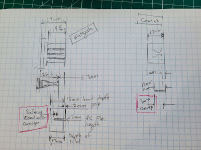
I've done the math again, and the results between the electrical measurements and mechcanical are consistent.  For this part of the converation "overlap" does not take into account electrical resistance.  It refers to the overlapping, theoretical conductor lengths alone. On the left I have  the important dimensions of the Wattgate.  The case is black so I can't see it and have to derive the distance from the pin to the end of the case as 6.7mm. Further, I have to infer the amount the pin sticks into the plug as well. 

Based on all of this it seems that the total conductor overlap in Wattgate is barely 3.3 mm, vs. 9 mm for Connex.  This is consistent with the electrical overlaps (previously discussed) of 0R being 2mm vs. 5.

Let's look at what 3.3 mm looks like.  I've placed my steel pocket ruler under the pins and set the depth bar to 3.3 mm:


What's interesting is that this means the pins barely get to the belly of the outlet.  What's going on?  
 

How Wattgate Grips

Each of the 3 pins in the connector are in a 5 mm wide plastic channel.  When gently pressed closed the flare at the end of the pins is 4mm wide.  This means that after the pin spreads 1mm it must deform in order to accommodate the wider male pin on the inlet.  Per spec, these are 2 mm. 

Connex Insert Depth

I took a similar picture with the transparent Connex, but here I set the depth gauge to 12mm, the actual length of the pin. This isn't apples to apples because above I can't show you the 6.7mm of the extra body length or the 2mm of gap.  The Connex fits to the bottom, so the entire 12mm pin length is inserted:


As you can visually gauge, when fully inserted the pin will make it just to the end of the contact area of the pins. 

This is, again, why Connex has 5mm of 0R travel but Wattgate has 2. 

The design of the plug and inlet doesn't leave a lot of play in the manufacturing.  3-5mm differences in length can cause significant differences in reliability.


Conclusion

The Wattgate reputation for being tight overshadows it's performance as a conductor of high current electricity.  It seems the entirety of the reputation is based on how well it is grip without appropriate thought given to ensuring the hot and neutral pins make significant contact. 

One can argue that who cares if it's tight?  Well, in my testing the Wattgate gets tight, but even minor side to side movements can cause disconnects.  So it may feel tight, but it's not secure.  The Connex can pull out more easily, but it maintains it's electrical function far longer and better than Wattgate.   

At no point in any of my many attempts with a variety of inlets did the Wattgate seat (hit bottom) fully unless the pins were removed. 

Having this sample and this measurements I am too concerned about the safety and reliability of the Wattgate plug to recommend it anywhere for anything.  I think it should be avoided for life safety issues.  The Connex brand may be inexpensive and more pretty than high tech but it 100% does the job better than Wattgate, and the screws don't strip out. I will feel safe putting this back into my system now. 

I find it interesting that the package for the Wattgate includes a filler plug to fill in the channel opposite the ground socket.  The instructions say that it's built to conform to UL specs, but just in case you need a little extra support, use the filler. Makes me honestly wonder how aware they are this is an issue already.  

The best I can say for Wattgate is that it very tightly grips the very end of the inlet pins.  In my circumstances I found this inadequate to account for even minor movements of the cable.  A little side to side movement and, despite the grip, the AC would disconnect. The Connex plug is not as tight but in a good inlet is firm and smooth, and is much less susceptible to cable motion. Fully inserted it's just not as likely to disconnect or arc.  The Wattgate may not pull out but your device will be disconnected.  It's not for me. 

Hypothesis

After doing further analysis I think the Wattgate plug is deliberately longer than the pins so that it can give the illusion of being more inserted than it actually is. It's almost like when you buy a box of cereal and find it half empty.

Test it Yourself

This seems like a lot to do but  if you are curious and have a Wattgate 320i, there's a very simple test you can do and tell me about your results.  Put masking tape on the top of it and mark it 17mm from the end.  Then stick it in whatever you have been using it on and mark that.  If you find the inlet is short of fully seating, mark it and tell me what you found.

Disclaimers

I think it's pretty clear that I'm just one guy enjoying his hobby and sharing his testing.  If you feel I have posted in error I strongly encourage you to test yourself, and blog about it, and let me know and I'll be happy to link to it, or  if you feel I made a basic error of measurement also please let me know in the comments.  The Wattgate plug is going in the trash though so I won't be redoing that work. 
 
Assuming my insertion strength was not good enough, I have to say a plug that doesn't seat properly 15% of the time is not safe, regardless of who is at fault.  That is, if the average user fails to use it properly 15% of the time it's clearly a problem.